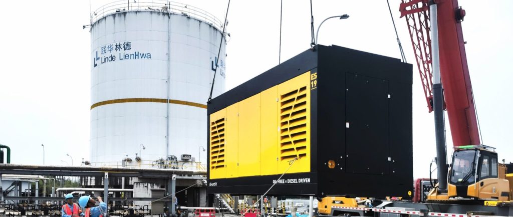
Air separation equipment, commonly referred to as Air Separation Units (ASUs), are industrial systems designed to separate the components of atmospheric air and produce oxygen, nitrogen, argon, and rare gases such as helium, neon, krypton, and xenon. These systems are widely used in metallurgy, modern coal chemical processes, nitrogen fertilizer production, and industrial gas supply.
The core principle of an ASU is to compress and deeply cool air until it liquefies, and then use fractional distillation to separate each gas component according to its boiling point.
1. Overview of the Air Separation Process
A complete ASU typically consists of nine major subsystems:
- Air Compression System
- Pre-Cooling System
- Purification System
- Heat Exchange System
- Expansion and Refrigeration System
- Rectification (Distillation Column) System
- Cryogenic Liquid Pump System
- Product Delivery System
- Product Compression System
Below is a step-by-step overview of each system and its core equipment.
2. Air Compression System
Key components include the steam turbine, main air compressor, booster compressor, instrument air compressor, and self-cleaning air filters.
- Steam Turbine: Typically in condensing-extraction mode, uses high-pressure steam to drive the compressor shaft.
- Main Air Compressor: Usually a single-shaft, isothermal, multi-stage centrifugal type with four compression stages and three intercooling stages; equipped with a washing system for rotor maintenance.
- Booster Compressor: Available in single-shaft or gear-driven centrifugal types; gear type offers better efficiency under high-pressure conditions.
- Instrument Air Compressor: Options include oil-free screw, piston, and centrifugal types; selection depends on air volume and required purity level.
- Self-Cleaning Filter: Configured based on air volume; installed at the windward inlet to ensure clean air intake.
3. Pre-Cooling System
Pre-cools the compressed air before purification to ensure the effectiveness of the molecular sieve system.
- Circulation Modes:
- Closed-loop (for poor water quality conditions)
- Open-loop (widely used, but requires makeup water)
- Air Cooling Tower: Filled with multiple layers of stainless steel and polypropylene Pall rings to increase heat exchange efficiency.
- Water Cooling Tower: Available in single-stage or dual-stage designs depending on the availability of external cooling sources.
All water inlets are equipped with filters. Temperature probes are installed inside cooling towers to monitor performance.
4. Purification System
Removes moisture, CO₂, and hydrocarbons from air to protect downstream cryogenic components.
- Types of Adsorbers:
- Vertical axial-flow (for units <10,000 Nm³/h)
- Horizontal dual-layer beds (for medium to large units)
- Vertical radial-flow (for >20,000 Nm³/h; space- and energy-efficient)
- Regeneration Methods:
- Electric heating or steam heating
- Safety valves and throttling loops ensure stable regeneration cycles
5. Heat Exchange System
Transfers thermal energy between streams to pre-cool incoming air and recover cold energy from outgoing product gases.
- Design Principle: Multi-stream auto-balancing to optimize energy usage.
- Configuration: Above 20,000 Nm³/h, high- and low-pressure exchangers are separated to reduce investment; below that, full high-pressure exchanger design is used.
6. Expansion and Refrigeration System
Expansion turbines (expanders) provide deep refrigeration by converting pressure energy into cooling.
- Types: Low-pressure, medium-pressure, and liquid expanders.
- Startup Procedure: Includes purging, sealing gas supply, oil circulation, interlock testing, and thermal stabilization.
- Liquid Expanders: Common in large internal compression units (>40,000 Nm³/h), offering ~2% energy savings but requiring high investment.
7. Distillation Column System
Separates liquefied air into oxygen, nitrogen, and argon via fractional distillation.
- Lower Column: Typically uses sieve trays, packed columns, or circulation trays depending on scale.
- Upper Column, Crude Argon Column, Pure Argon Column: Usually packed; commonly supplied by Sulzer or Tianjin University suppliers.
- Layout Options: Up to six configurations available based on cold box space, process routing, and elevation requirements.
8. Cryogenic Liquid Pump System
Transfers cryogenic liquids from storage to downstream high-pressure applications.
- Horizontal Pumps: Compact, low-pressure applications; limited rotational speed.
- Vertical Pumps: Preferred for high-pressure; excellent balance and sealing.
Auxiliary systems include gas purging lines, heating circuits, sealing gas, drain/vent valves, and recirculation piping.
9. Product Delivery and Compression System
Delivers separated gases to users or compresses them for storage and transport.
- Low-Pressure Products: Equipped with control valves and silencers to maintain pressure stability.
- High-Pressure Oxygen/Nitrogen: Multi-stage throttling with silencers; oxygen systems require anti-explosion materials and remote control configurations.
- Product Compression: Gear or turbo compressors are selected based on gas type; oxygen systems use copper-alloy flow paths and require inert gas sealing for safety.
This comprehensive overview outlines the functional structure of a modern air separation unit. Effective integration and operation of each subsystem are critical to ensuring safe, efficient, and long-term stable performance of industrial gas production systems.


